

No products in the cart.
-54%


Module
PC817 4 Channels Optocoupler Isolation Module
Availability:
Out of stock
LKMOD00169
Rs 550.00
Out of stock
PC817 4-Channel Optocoupler Isolation Module
Specifications
Core Components
- Optocouplers: 4 × PC817 optocoupler
(Each contains an infrared LED + phototransistor for signal isolation)
Purpose
- Provides electrical isolation between the input and output sides
- Protects microcontrollers and sensitive circuits from noise, high voltage, or spikes
- Commonly used for isolating:
- Digital signals
- Control signals
- Communication lines
Electrical Characteristics (Typical, per Channel)
- Input (LED) Forward Voltage: ~1.2 V
- Input Forward Current: max ~20 mA
- Output Phototransistor Collector‑Emitter Voltage: max ~30–35 V
- Current Transfer Ratio (CTR): typically 20%–50%
Module Input
- Channels: 4 isolated input channels
- Signal Type: digital (logic/TTL)
- Inputs from microcontrollers (5V logic) or other driving circuits
- Often includes input current‑limiting resistors on board
Module Outputs
- Open‑collector phototransistor outputs (active when the input LED is driven)
- Typically requires an external pull‑up resistor on the output side (sometimes included on board)
Power and Supply
- Some variants may require a module VCC to power pull‑ups
- Input and output sides are galvanically isolated
- Isolation voltage rating (between input and output):
- Typically ≥ 3 kV (3000 V) (depends on board design)
Interface
- Standard 2.54 mm (0.1″) header pins
- Typical pin layout:
- 4x Inputs (IN1–IN4)
- 4x Outputs (OUT1–OUT4)
- GND / VCC (depending on version)
SKU: LKMOD00169
Category: Module
Based on 0 reviews
0.0 overall
0
0
0
0
0
Be the first to review “PC817 4 Channels Optocoupler Isolation Module” Cancel reply
You must be logged in to post a review.
Related products
- Module, Sensors
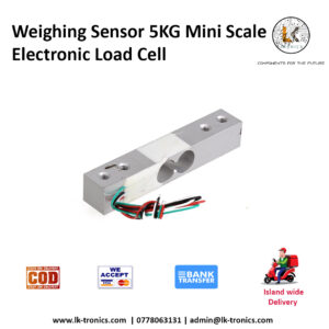
Weighing Sensor 5KG / 10KG / 20KG Mini Scale Electronic Load Cell
0 out of 5(0)LKSEN00031 | LKMOD00129 | LKMOD00130
SECTION: 4 RACK: E
SKU: LKSEN00031Rs 450.00 This product has multiple variants. The options may be chosen on the product page

There are no reviews yet.